CIS-E Fuel Adjustment
Over time, the CIS-E injection system's factory calibrated settings may no longer be optimal due to wear and tear, aging, or outright replacement of fuel system components. Correcting the air/fuel mixture is important in order to keep the engine running at it's best.
Fortunately, there is a way to diagnose the injection system's fuel mixture using built-in diagnostics by means of an on/off ratio, or duty cycle, to determine rich or lean air/fuel mixtures. This is a signal that is output from the CIS-E control unit to the X11 port located inside the engine bay on the left fender. Mechanical adjustments for the fuel mixture are performed at the air flow meter and inside the Electro-Hydraulic Actuator (EHA) valve.
Switching KE Control Unit to Duty Cycle Output
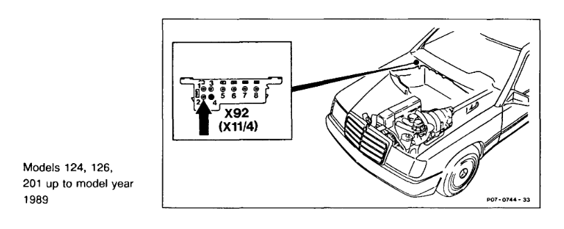
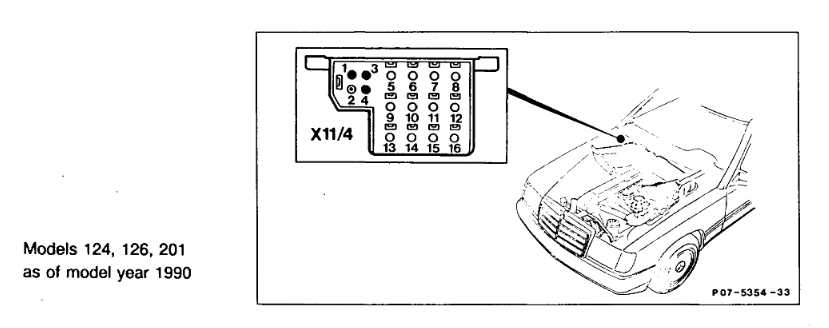
The KE Control unit needs to be switched into a special mode in order to read the fuel trim with the on/off ratio at the X11 diagnostic port. Switching to the special diagnostic mode is performed at the X92 (X11/4) unit located near the battery.
Fault code memory needs to be read out until there are no faults left.
- Key on position with engine off
- Hold the push button switch on the X92 (X11/4) unit for 5 seconds
- Count 1 pulse from the LED. If there are multiple pulses, clear all of the faults on the control unit and start over.
- Hold the push button switch again for 5 seconds
- LED should remain on
At this point, the control unit should be in the diagnostic mode for outputting the fuel trim as an on/off ratio. After this, when the engine is started, the CHECK ENGINE LIGHT should be illuminated.
Note: Some ECUs do not require being put into a diagnostic mode and will begin outputting a duty cycle reading after 30 seconds of idle time after the engine has been started.
Reading the on/off ratio
The on/off ratio can be read at the X11 port. Pin 3 is the signal and pin 2 is the ground.
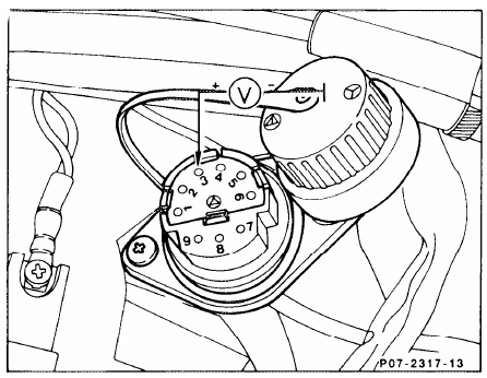
As of 1987, the on/off ratio is represented as a 100 hz pulse and can be read with an oscilloscope or a multimeter capable of interpreting duty cycle. However, not all multimeters can read duty cycle as a feature. Check your owners manual for specifics on this operating mode.
Known multimeters that can read duty cycle include:
The CIS control unit uses an inverse duty cycle interpretation. In other words, constant 0V is considered 100% duty cycle. Therefore, for simplicity sake, reverse the leads on the multimeter to more easily understand the duty cycle. Positive lead on the multimeter or oscilloscope will be placed on pin 2 (ground) and the negative lead will be on pin 3 (on/off ratio). Note: reversing the leads is only a trick for using a device that reads duty cycle in the conventional sense where the amount of time spent at the higher voltage corresponds to the duty cycle percentage.
If your multimeter cannot interpret duty cycles, there is a mathematical way to convert a voltage to a duty cycle:

Example: Battery voltage is 13.4 V, pin 3 is reading 10.0 V, giving us a duty cycle of 25.37%.

Performing Adjustments
The adjustment procedure can be generalized as follows:
- Engine is at operating temperature, 80C
- Record average duty cycle at engine idle
- Record average duty cycle at engine speed of 2500 RPM
- Adjust EHA valve and adjustment screw on fuel distributor until duty cycle for engine speeds at idle and 2500 RPM are near 50% and within 10% of each other
Adjusting EHA Valve
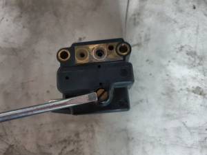
- Remove EHA valve from fuel distributor
- Unplug wire connector
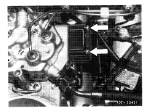
- Remove 2 screws holding EHA valve to fuel distributor while covering the EHA valve with a rag to catch fuel that will squirt at your face
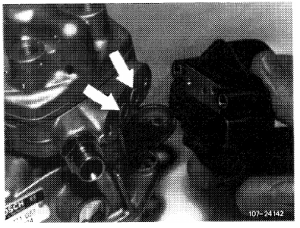
- Pull EHA valve off fuel distributor, noting the 2 green rubber sealing rings.
- Remove the screw cover with a flathead screw driver
- Use a 2mm allen key to turn the adjustment screw inside the EHA valve with small adjustments (1/4 turn at a time)
- Turn clockwise to enrichen the fuel mixture. This decreases the duty cycle or increases the voltage, depending on whatever method you are using.
- Turn counter-clockwise to lean the fuel mixture. This increases the duty cycle or decreases the voltage, depending on whatever method you are using.
- Reinstall EHA valve
Adjusting Fuel Distributor Screw
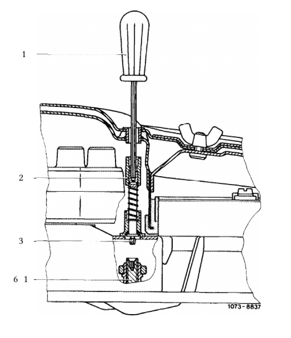
If there is a steel plug present, it needs to be drilled out first. Engine must be idling for this adjustment.
- Insert 3mm allen key or screwdriver into the adjustment tower.
- Push down against spring until the screw fully contacts the mixture setting screw. Pushing further past this point will cause engine to stall.
- Turn clockwise to enrichen the fuel mixture. This decreases the duty cycle or increases the voltage, depending on whatever method you are using.
- Turn counter-clockwise to lean the fuel mixture. This increases the duty cycle or decreases the voltage, depending on whatever method you are using.
- Use small increments for adjustments such as 1/4 of a turn while checking the new duty cycle or voltage to avoid making large changes that could cause the engine to stall or not start.
