Overvoltage Protection Relay
Function
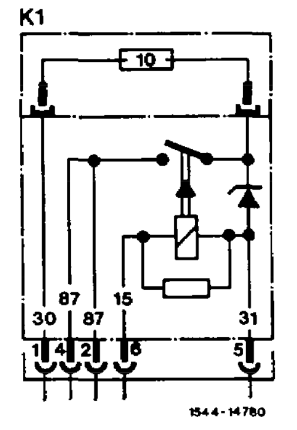
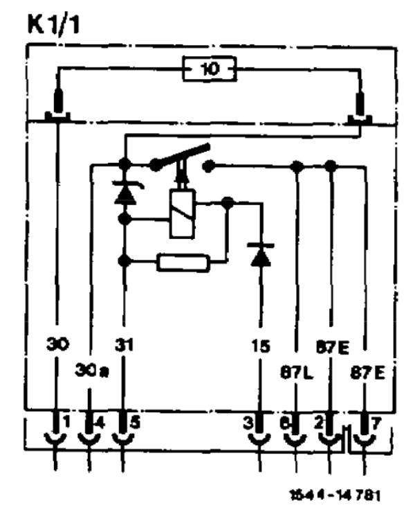
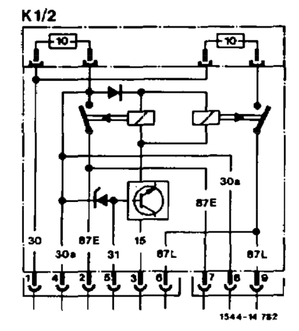
A 5, 7, or 9-pin overvoltage protection relay is installed depending on the vehicle model and special equipment. This relay protects the control units (ABS, CIS-E, etc.) from excessively high voltage.
The battery voltage is present continuously at relay terminal 30. With the 7 and 9-pin versions the battery voltage is also connected to terminal 30a over the 10 A flat plug-in fuse. When the ignition/starter switch is turned to position 2 (driving position), the voltage is present at terminal 15 causing the relay to pull in. Power is supplied to terminals 87 (5-pin version) or 87E and 87L (7 and 9-pin versions).
Voltages > 22 V in the vehicle electrical system are connected directly to ground by the Z diode (fuse defective).
In the event of overloads occurring after the overvoltage cutout, the circuit is interrupted by the 10 A flat plug-in fuse. The 9-pin version is also fused separately at terminals 87E and 87L, whereby when the fuse for 87E blows 87L is also switched off.
Diagrams and Pinout
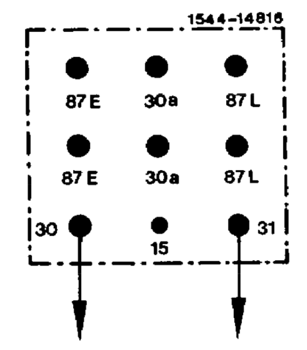
Pinout
| Pin | Function |
|---|---|
| 30 | Battery voltage input (12 V) |
| 31 | Ground |
| 15 | Ignition switch input |
| 87E | Fused and diode protected output (12 V) |
| 87L | Fused and diode protected output (12 V) |
| 30a | Fused output (12 V) |
Testing
The following procedure is a static test for basic relay operation. Passing the following test does not guarantee that the OVP relay is functioning correctly, but will accurately tell if the OVP relay is faulty.
- Apply 12V to pin 30 and ground 31
- Verify with a multimeter that 30a has 12V and 87E/87L has no voltage
- Apply 12V to pin 15
- The internal relay should click
- Verify with a multimeter that 87E and 87L have 12V as well as 30a.
Part numbers
Part Numbers for OVP Relay
| Part Number | Description |
|---|---|
| 201 540 32 45 | 7-pin relay, black top, single 10A fuse |
| 201 540 38 45 | 7-pin relay, black top, single 10A fuse |
| 201 540 37 45 | 9-pin relay, red top, double 10A fuse |


