This is an old revision of the document!
M104.98x
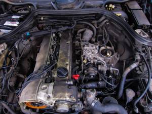
This 3.0 L (2960 cc) 24v DOHC was introduced as a sports car resp. top model completing the line-up of M103 12V engines. M103 and this engine were replaced by the later 2.8l and 3.2l versions of M104. It was found in the W124 300E-24 models, C124 300CE-24 models, T124 300TE-24 models and R129 300SL-24 models. The 3.0 L M104 produced 217 hp (162 kW) to 228 hp(without catalytic version) and features KE-Jetronic fuel injection, cylinder specific ignition-timing, variable valve timing and under-piston cooling jets. 1)
Engine Oil
Filters
M104 engines use a cartridge filter and can be ordered from the dealer using part number 104 180 01 09, but aftermarket kits can be purchased from automotive retailers referencing the table below. Kits should come with a new seal ring for replacement on the filter cap.
Filters
| Brand | Part number |
|---|---|
| WIX | 51145 |
| K&N | PS7008 |
| MicroGard | MGL51145 |
| ACDelco | PF2146 |
| Bosch | 72194WS |
| Mann | HU7271X |
Fluid
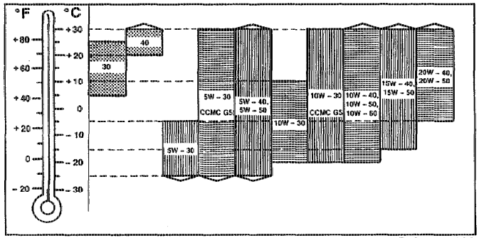
A list of compatible fluids for this engine can be found within the 229.3 oil specifications. Engine oil capacity including filter requires 7.0 liters of oil. Use the chart below as a guideline for choosing correct oil weights.
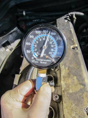
Compression Pressure Test

- Warm engine to operating temperature
- Remove ignition coil wire to distributor
- Remove spark plug
- Insert compression pressure measuring device into spark plug
- Crank engine for at least 8 revolutions
- Read value and reinstall spark plug
- Repeat for all cylinders
Cylinder Head
Removal
- Disconnect battery
- Drain coolant at radiator and engine block
- Remove exhaust manifold
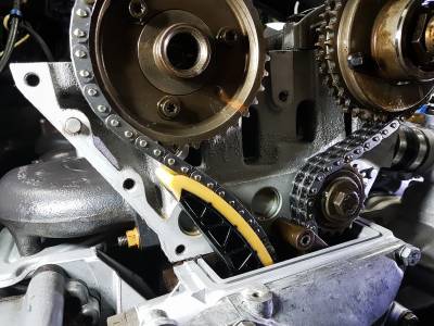
- Remove upper timing cover
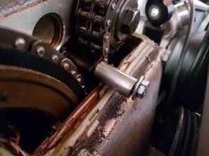
- Remove guide pin rail with extractor
- Use washer/bolt as a makeshift puller. Thread size is M6x1.0
- Remove timing chain tensioner
- Remove exhaust camshaft chain gear, T30
- Remove lower guide sprocket, left handed thread 17mm
- Pull chain off the intake camshaft gear and set aside
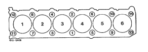
- Unbolt cylinder head in reverse of tightening order with the following 3 stages (M12 triple square socket)
- 90 degrees starting with bolt #14 → #1
- 90 degrees starting with bolt #14 → #1
- Unscrew and completely remove bolt starting with #14 → #1
- Loosen water pump hose
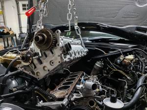
- Lift cylinder head out
Prepare for install
Cylinder Head
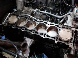
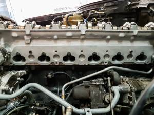
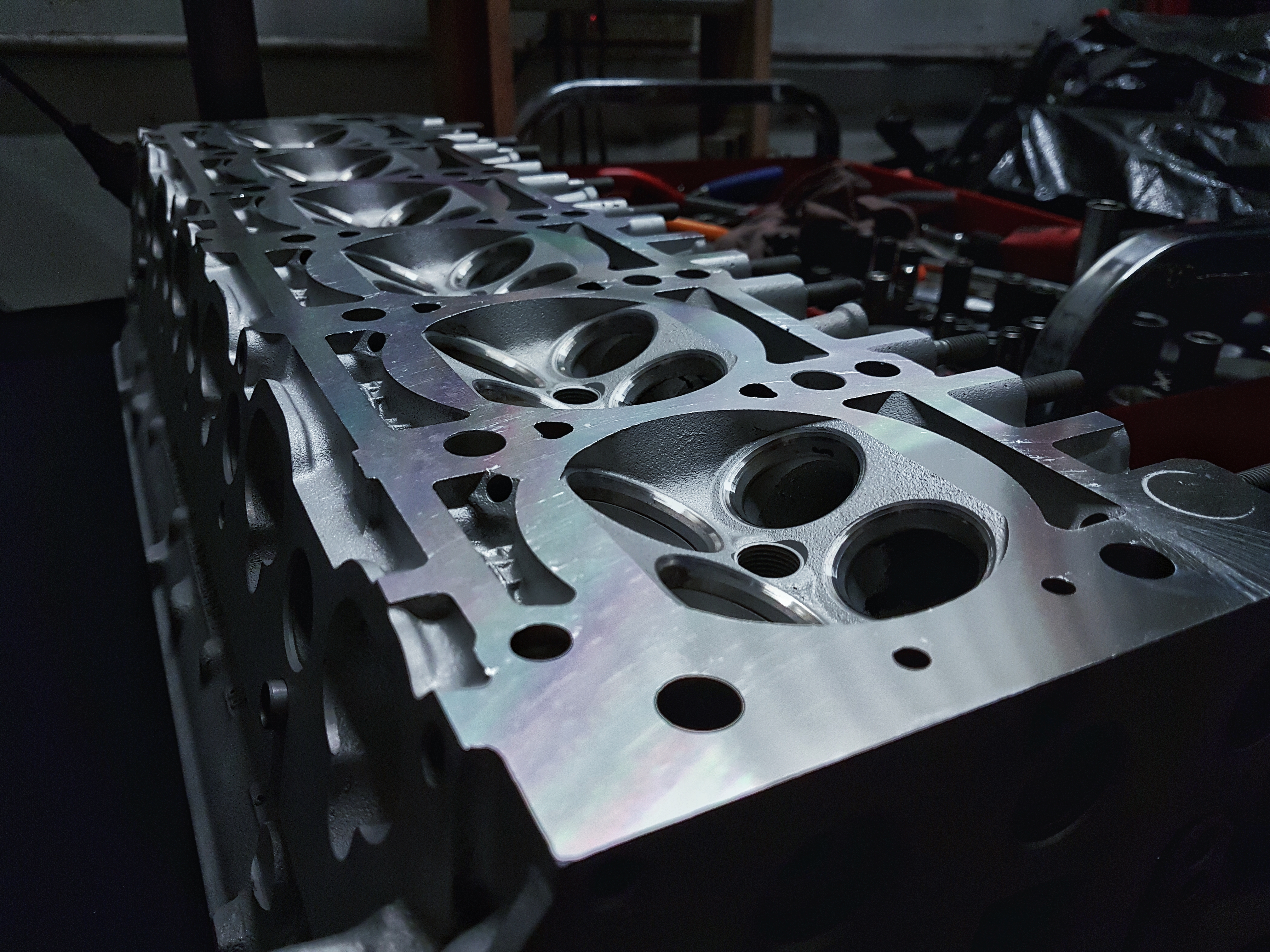
While the cylinder head is off, it's recommended to send it off to a machine shop to have the mating surface refinished and the valve stem seals replaced at the very least. Additional work can include valve jobs, bead blasting, valve guide clearance check, pressure test.
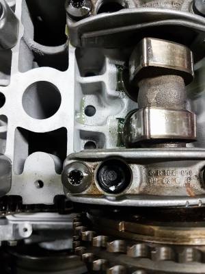
Note: The cylinder head bolt washers are located inside the camshaft bearing caps. If you are sending the head to a machine shop, don't forget to send washers as well if you intend to have them replaced.
Engine Block
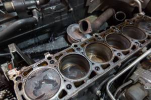
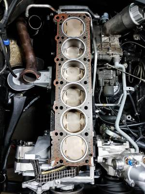
The piston tops can be cleaned off if there are carbon deposits on the top. Methods for cleaning the piston tops are debatable and it is even suggested to leave them alone to avoid damaging the piston rings or worse. The damage occurs when either the carbon deposits or abrasive materials (aluminum oxide from maroon Scotch-Brite pads, silicon carbide from grey Scotch-Brite pads) fall down the cylinder walls and rest on top of the piston rings. Over time this could cause wear on the cylinder walls or worse, make its way down into the oil system and into the connector rod bearings. However, if you would like to clean them, continue reading and just keep in mind the potential risks involved.
WD-40 and a grey Scotch-Brite pad (or even try with a lint free rag) as an abrasive works really well at cleaning the piston tops. Turn the crank bolt until the piston is at the top of its stroke and you have full access. Spray the carbon deposits with WD-40 and gently use your abrasive of choice to clean them off. Wipe down the area with a lint free towel or rag. Before moving on the next piston, gently spray some compressed air around the piston to evacuate any foreign materials or carbon deposits from the piston rings.
Installation
- Fit head gasket onto engine block
- Lower cylinder head onto engine block
- Oil cylinder bolt threads and head mating surface and torque bolts in 3 stages following the tightening order.
- Stage 1: 55 Nm
- Stage 2: 90 degrees
- Stage 3: 90 degrees
- It is helpful to mark the bolt with a small dab of paint at the 12 o'clock position after stage 1 to keep track of how many degrees the bolt has turned.
- Setup basic timing
- Install timing chain guide sprocket. Tighten to 35 Nm, reverse threaded.
- Setup TDC for crankshaft, intake camshaft, and exhaust camshaft
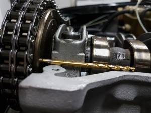
- There are 4mm holes located on the camshaft flanges. Stick a 4mm allen or a 5/32 drill bit in the hole and align camshaft until the hole is flush with the surface of the head
- Rotate intake camshaft gear clockwise until stop. This puts the camshaft in retarded position.
- Pull chain up and over the intake camshaft
- Install exhaust camshaft sprocket with chain
- Avoid turning and checking the timing until after the upper timing cover and chain tensioner are both installed. Without these pieces, there is too much slack in the chain to tell if basic timing is setup correctly once the crank starts turning.
- Install guide rail pin
- Install upper timing cover with guide rail
- Install chain tensioner
- Check timing by rotating the engine through one entire combustion cycle. Check alignment of camshafts and crankshaft.
- Install exhaust manifold
Complete Engine Removal
- Optional: Remove front bumper for extra clearance for shorter reaching engine hoists
- Optional: Remove alternator for extra clearance when pulleys are interfering with cross member
- Optional: Remove transmission cooler lines for extra clearance when the lines interfere with cross member
- Optional: Drain engine oil. (Task is easier to manage when motor is still in a car chassis)
- Remove bottom engine tray
- Remove air cleaner box
- Remove radiator
- Remove viscous fan clutch assembly
- Power Steering
- Drain power steering reservoir
- Remove suction pipe
- Remove high pressure pipe
- AC
- Remove poly v-belt
- Remove air compressor with hoses still attached
- Remove condensor
- Disconnect fuel pipes at fuel distributor
- Disconnect accelerator cable and transmission bowden cable
- Disconnect heater supply and return hoses
- Disconnect vacuum lines by brake booster, to transmission, to EZL unit, EGR pipe, and smog pump
- Disconnect brake booster line at intake manifold
- Electrical connections
- Disconnect oil pressure sensor and oil level sensor
- Disconnect main engine wiring harness
- Disconnect crank position sensor and knock sensor at EZL
- Disconnect TD signal at X11 and unbolt X11 connector from fender
- Disconnect starter bracket at rear of intake manifold
- Disconnect ignition coil from distributor
- Unplug alternator
- Unplug smog pump
- Exhaust system
- Disconnect down pipes from manifold
- Unbolt support bracket on transmission
- Automatic Transmission
- Remove transmission mounting plate
- Disconnect speedometer cable at transmission rear
- Disconnect ground cable at bell housing
- Disconnect kickdown solenoid
- Disconnect starter lockout wire
- Disconnect transmission overload
- Disconnect shift rod
- Disconnect flex plate from transmission output flange
- Unbolt motor mounts from underneath
- Secure engine with hoist and remove engine with transmission attached
- Unplug starter wires as engine is being lifted
- Remove fuel cooler mounting bracket from block
Fan shroud
Removal / Installation
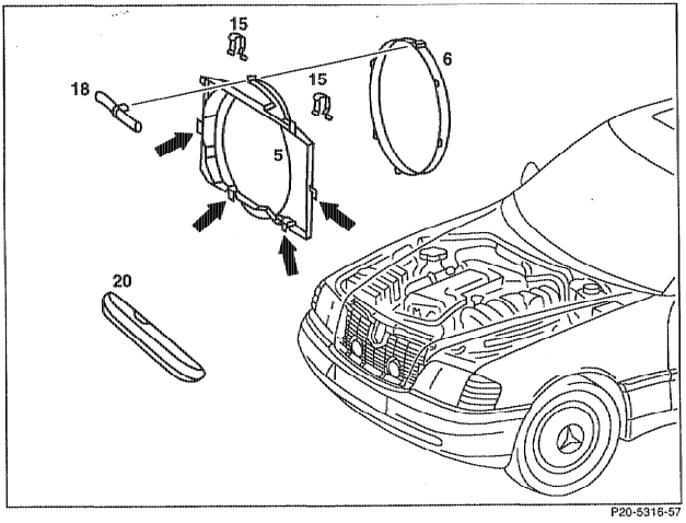
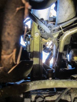
- Remove locking pin (18)
- Rotate fan shroud ring (6) to open position and separate
- Remove retaining spring clips (15)
- Lift fan shroud and fan shroud ring to remove
- Install in reverse procedure
Fan clutch
The M104.98x engines share the same fan clutch as the older M103 predecessor. The part number for the viscous fan clutch is 103 200 04 22
Special Tool
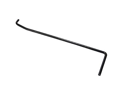
A special tool is required to counter-hold the fan clutch while loosening the 8mm allen hex bolt in the center. The part number for this tool is 103 589 00 40 00.
Removal
- Remove fan shroud
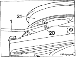
- Rotate fan with the 8mm allen hex bolt to align the counter-hold tool into a retaining hole behind the pulley.
- While applying pressure on the counter-hold tool, loosen the 8mm hex allen bolt
- Remove fan clutch and fan blade assembly together
Poly V-belt
Removal
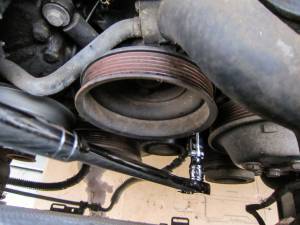
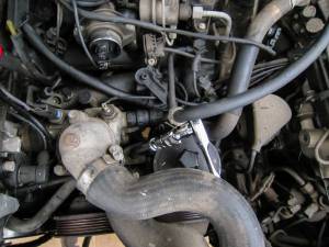
Installation
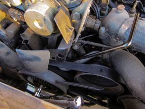
- Route new belt according to diagram
- Tension the belt using 13mm adjustment rod
- Tighten until belt tensioner pointer is at max (leftmost)
- Tighten 10mm allen hex bolt in center of belt tensioner to 75 Nm
Belt Tensioner
Removal
- Loosen bolts on pulleys for water pump, power steering pump, and fan clutch
- Remove pulleys on water pump, power steering pump, and fan clutch
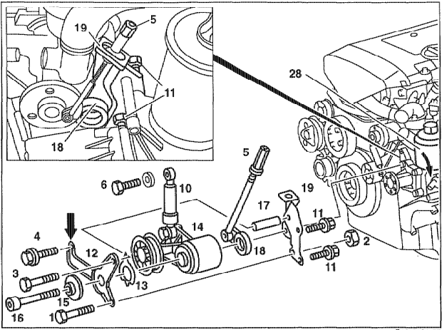
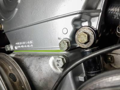
- Remove top bolt (6) of belt tensioner damper to front cover, 13mm hex
- Remove center bolt to belt tensioner (16), 10mm allen
- Remove 3 bolts on Y-bracket (1), (3), and (4) and remove Y-bracket
- Note: Bottom right bolt (1) has counter-hold nut (2)
- Remove setting pointer (13), belt tensioner (14), damper (10) and adjustment rod (18)
Installation
- Install belt tensioner (14) with setting pointer (13), damper (10) and adjustment rod (18)
- Align damper (10) and install top bolt (6), 13mm hex
- Pointer set to lowest point (rightmost)
- On Y-bracket, apply sealing compound on end that attaches to the fan bearing bracket. Apply to both front and rear of bracket.
- Install bolts to 21 Nm, 13mm hex
- Install center bolt to belt tensioner (16), 10mm allen
- Do not tighten until belt tension has been set
- Install pulleys on water pump, power steering pump, and fan clutch
- Install poly v-belt
- Install viscous fan clutch
- Install fan shroud
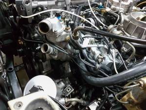
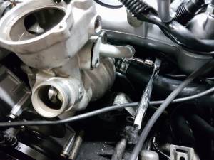
Water Pump
Removal
- Remove air cleaner
- Drain coolant from radiator and engine block
- Remove radiator
- Remove 13mm hex bolt holding power steering pump to rear belt tensioner bracket and set power steering pump aside with hoses connected
- When this bolt is loosened, the sleeve for the upper belt tensioner bracket bolt will fall off.
- Optional, but highly recommended for creating more space for accessing the upper right bolt
- Remove idle air control valve
- Remove dipstick
- Remove heater return pipe
- Remove thermostat cover and thermostat
- Disconnect and remove sensors from water pump
- Loosen hose clamp for short hose to cylinder head
- Remove 10mm bolts on pipe to oil/water heat exchanger
- Remove water pump bolts
- Upper left - 6mm allen, accessible with 1/4 ratchet and a stubby 6mm allen socket
- Bottom left - 13mm hex, accessible with 1/4 ratchet with extension and wobble 13mm socket
- Upper right - 13mm hex, accessible with 1/4 ratchet with medium length extension and wobble socket from underneath the intake manifold
- Bottom right - 13mm hex, accessible with 1/4 ratchet with long extension and wobble socket from underneath the intake manifold
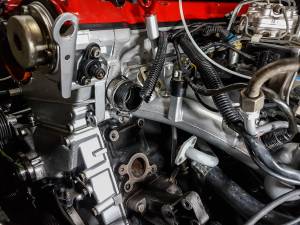
- Before pulling the water pump off, temporarily reinstall the dipstick if it was removed. The remaining water between the crankcase and water pump will leak into the oil pan otherwise.
Installation
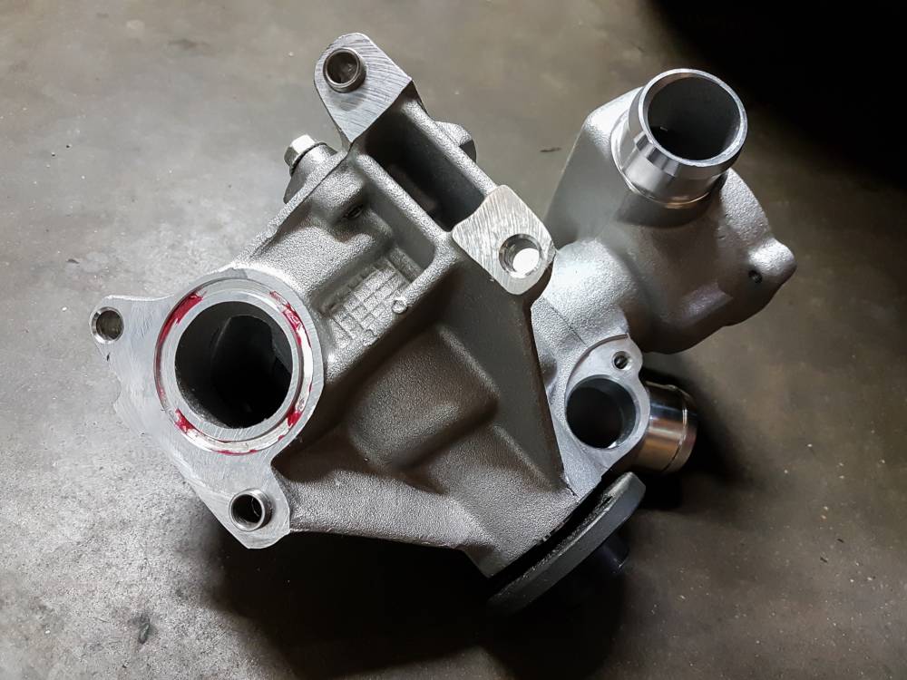
- Apply small dabs of grease to the main seal to keep it in place during installation
- Install smaller seal for oil/water heat exchange pipe
- Bolt water pump to crankcase, torque to 25 Nm
- Reconnect pipe for oil/water heat exchanger
- Tighten hose clamp for short hose to head
- Reinstall sensors
- Reinstall thermostat and thermostat cover, replace seal.
- Reinstall heater return pipe, replace seal.
- Reinstall idle air control valve and dip stick if removed.
- Reinstall the bracket that connects the power steering pump and belt tensioner
- Install belt tensionerInstall belt tensioner
- Install radiator
- Fill coolant, bleed, and check for leaks
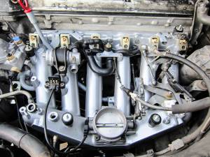
Intake Manifold
Removal
- Disconnect coolant hose and lifting hook at rear of cylinder head for clearance / maneuverability
- Disconnect vacuum lines including brake booster
- Brake booster: 19mm hex at intake manifold, 5mm allen at bracket
- Disconnect all electrical plugs and move engine wire harness out of the way
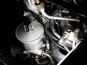
- Single pin connector that goes behind oil filter (need ID)
- EHA valve and idle microswitch
- Cold start valve, throttle position sensor (2), air intake sensor, and idle air control valve
- Coolant temperature sensors (2), grounding bracket, AC compressor switch, AC pressure switch, and EZL plug
- Coolant temperature sensor, camshaft position sensor, and camshaft advance solenoid
- Disconnect fuel supply/return lines
- Disconnect throttle linkages, bowden cable, and cruise control
- Remove dipstick tube, 2x 10mm hex bolts
- Disconnect crankcase breather hose between cylinders 2 and 3 on intake manifold
- From underneath
- Unbolt intake manifold mounting bracket located under cylinders 2 and 5, 13mm bolts
- Disconnect EGR pipe, 22mm nut
- Unbolt coolant pipe mount located behind (from underneath perspective) EGR pipe, 10mm
- Unbolt starter wire holder, 10mm
- Unbolt intake manifold bolts, 9x 13mm hex bolts
Fuel distributor
Removal
- Disconnect fuel supply and return lines
- Disconnect fuel pressure regulator mounting bracket, 10mm
- Remove fuel injector lines at valve, 12mm nut, 16mm on the injector valve to counter
- Including cold start valve
- Remove 3 top screws, T25
- Pull to remove
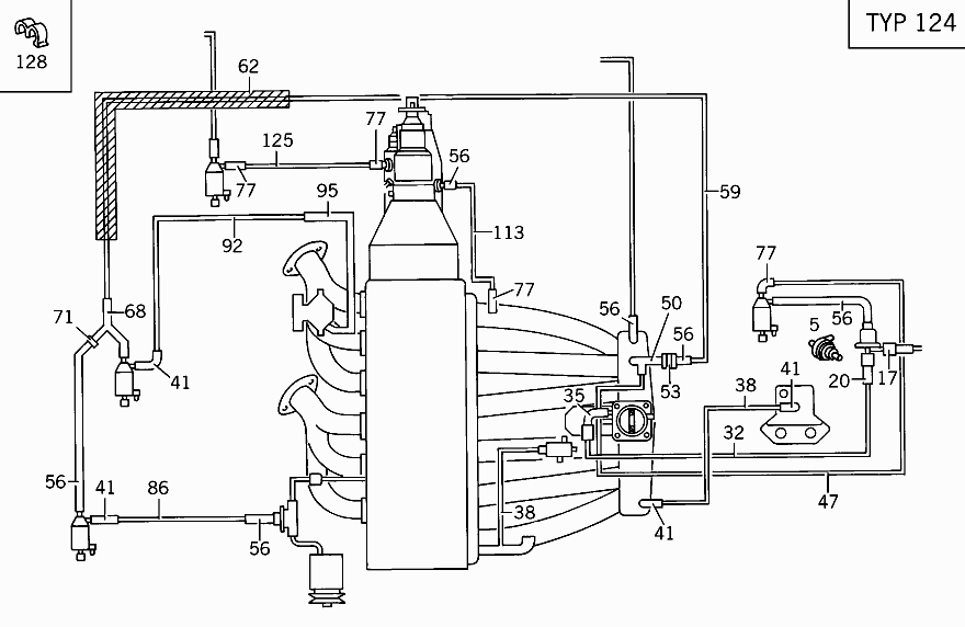
Vacuum System
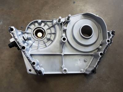
Upper timing cover
Removal
- Remove valve cover
- Remove distributor cap, rotor, mount, splash shield
- Remove upper chain rail
- Unbolt belt tensioner shock from timing cover
- Optional: Remove idle pulley for clearance to the lower left timing cover bolt
- Remove bolts for the timing cover and keep track of which bolts belong to which hole
- Long 13mm hex bolts located upper right of timing cover for the lifting hooks
- Shorter 13mm hex bolts located bottom left and bottom right nearest the u-seal
- Pry cover off
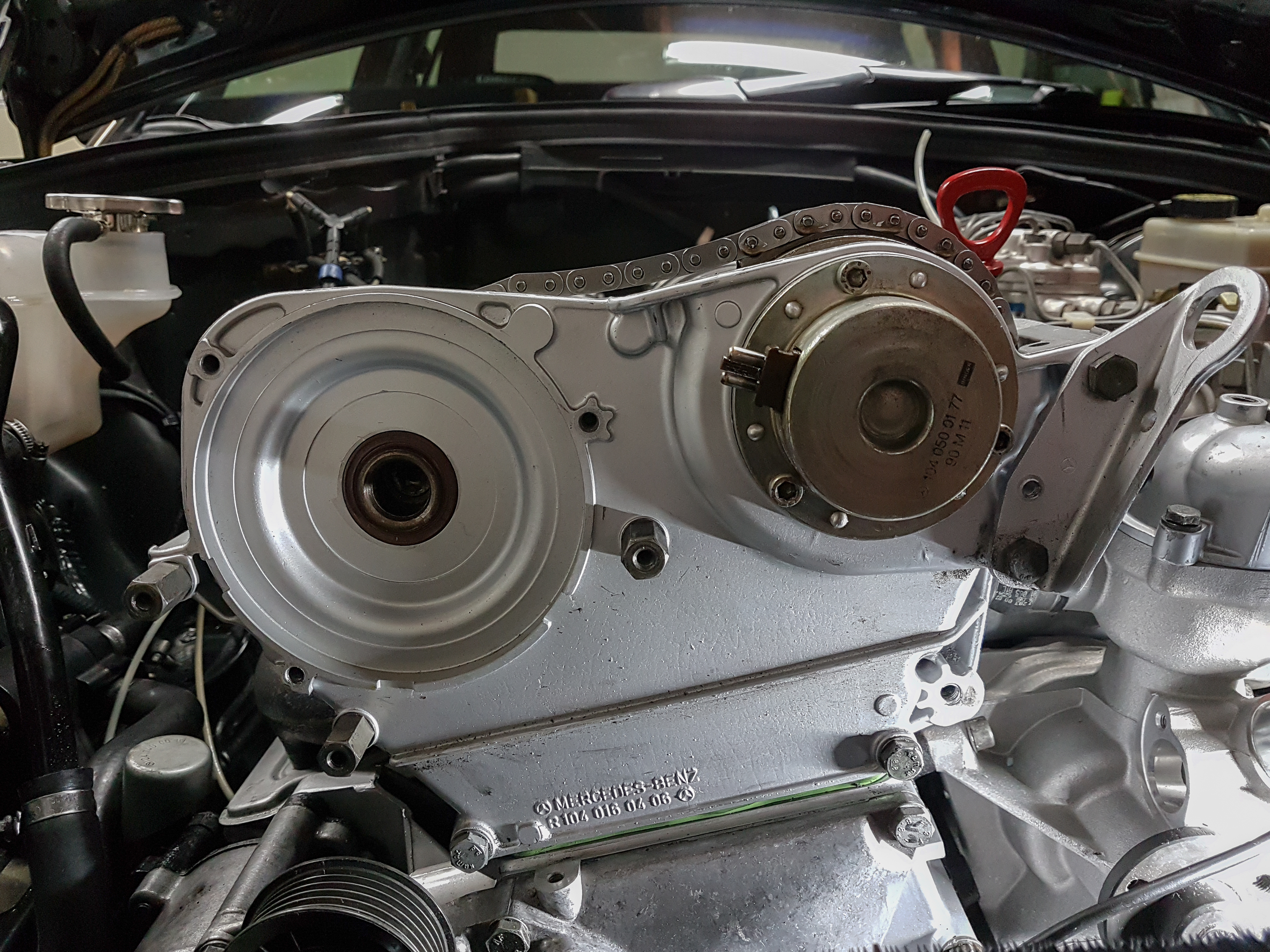
Installation
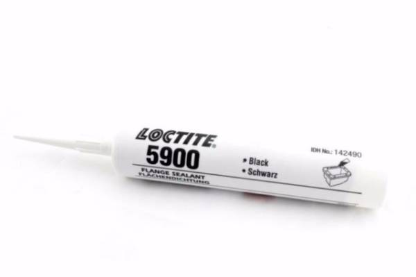
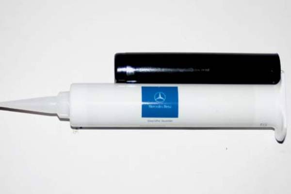
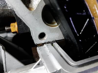
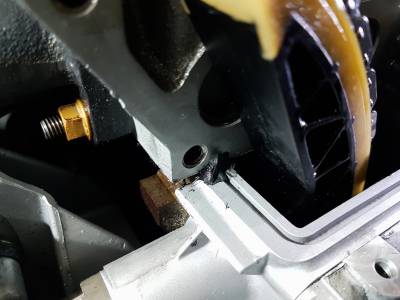
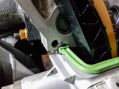
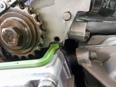
The metal to metal surfaces of the upper timing cover need a sealant applied before installation. Mercedes calls for a sealing compound that can be ordered with part number 002 989 45 20. Alternatives include Loctite 5900 and Permatex The Right Stuff.
- Clean mating surfaces of cylinder head, upper, and lower timing covers
- Apply sealant in the corners of the mating surfaces
- Install new rubber u-shaped seal and press the ends of the seal into the sealant
- On the exhaust side, apply another small layer of sealant across the top of the rubber seal. This corner tends to leak at any opportunity it has.
- Apply sealant to the mating surface of the timing cover. Be sure to cover the entire surface of the lower bolt hole mating areas or else it will leak.
- Apply a light coat of motor oil to the top of the rubber u-shaped seal allowing the timing cover to slide on without folding the seal over
- Assemble timing cover to cylinder head. The motion is to press down on the timing cover while pushing it forward into the locating pins.
- Secure the bottom two 13mm hex bolts first while continuing to press down on the timing cover
- Fasten the other timing cover bolts evenly and torque them to 25Nm
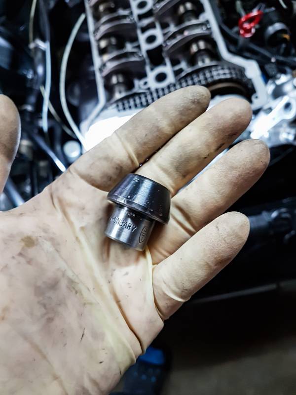
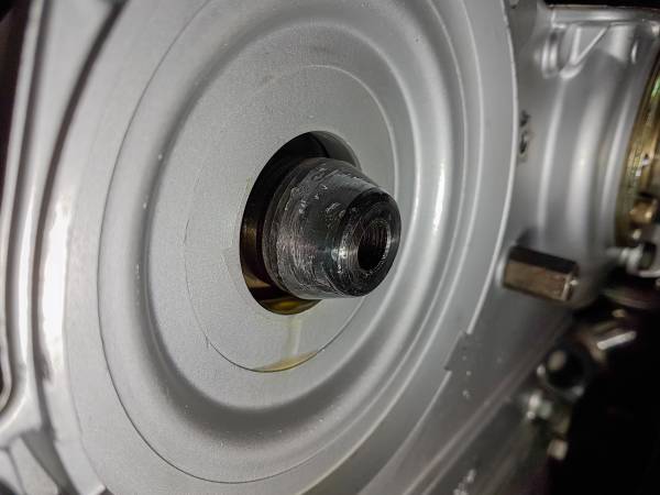
In addition to mounting the timing cover, the radial camshaft seal will need to be replaced. A special tool is required to install this seal properly
- Insert tool into the end of the camshaft
- Apply oil to the inside perimeter of the sealing hole and to the seal itself
- Slide the seal onto the tool and press in
- Remove the tool once the seal is no longer in contact with it
- Tap the seal in with a socket until seal is flush with surface
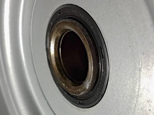
- If seal still leaks when flush with surface, then reinstall a new seal in a different position. A groove must have been worn at the previous location causing a leak.
